p5.jsでのシェーダー(GLSL)入門(4)図形を変形する
前回までフラグメントシェーダーを中心に、p5.js で書いた図形の描画を変化させてきました。
今回は頂点シェーダー(バーテックスシェーダー)を利用して、図形の位置や形を変えてみます。
GLSLで図形の変形
図形の移動
p5.jsで作成した図形をGLSLの頂点シェーダーを用いて、位置を移動させてみましょう。 フラグメントシェーダーは前回と同じ記述です。
let vs = `
   precision highp float;

   attribute vec3 aPosition;
   attribute vec2 aTexCoord;
   varying vec2 vTexCoord;

   uniform mat4 uProjectionMatrix;
   uniform mat4 uModelViewMatrix;

   void main() {
      vec3 pos = aPosition;
      pos.y += 1.0;
      vec4 positionVec4 = vec4(pos, 1.0);

      vTexCoord = aTexCoord;

      gl_Position = uProjectionMatrix * uModelViewMatrix * positionVec4;
   }
`;

let fs = `
   precision highp float;

   varying vec2 vTexCoord;

   void main() {
      vec2 b = vTexCoord * 2.0 - 1.0;
      vec3 col = vec3(pow(1.0 - abs(b.y), 8.0) * 2.0);
      col *= vec3(0.2, 0.5, 0.9) ;

      gl_FragColor = vec4(col, 1.0);
    }
`;

let theShader;

function setup() {
   createCanvas(500, 500, WEBGL);

   theShader = createShader(vs, fs);

   rectMode(CENTER);
   noStroke();

   const wh = 75 ;

   background("#B0D0B0");

   shader(theShader);

   push();
   translate(100, -150);
   rect(0, 0, wh, wh);
   pop();

   push();
   translate(100, 150);
   ellipse(0, 0, wh, wh);
   pop();

   resetShader();

   push();
   translate(-100, -150);
   rect(0, 0, wh, wh);
   pop();

   push();
   translate(-100, 150);
   ellipse(0, 0, wh, wh);
   pop();
}
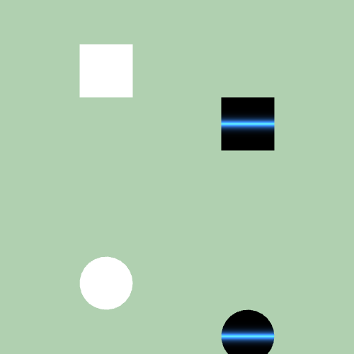
シェーダー適用した図形がy方向に移動していると思います。
頂点シェーダーのpos.y += 1.0;により、頂点が移動しています。
y方向に1.0、つまり画面下方向に図形の一つ分移動させています。
図形の拡大
続けて、図形を拡大させてみましょう。
let vs = `
   precision highp float;

   attribute vec3 aPosition;
   attribute vec2 aTexCoord;
   varying vec2 vTexCoord;

   uniform mat4 uProjectionMatrix;
   uniform mat4 uModelViewMatrix;

   void main() {
      vec3 pos = aPosition;
      pos.y *= 2.0;
      pos.y -= 0.5;
      vec4 positionVec4 = vec4(pos, 1.0);

      vTexCoord = aTexCoord;

      gl_Position = uProjectionMatrix * uModelViewMatrix * positionVec4;
   }
`;

let fs = `
   precision highp float;

   varying vec2 vTexCoord;

   void main() {
      vec2 b = vTexCoord * 2.0 - 1.0;
      vec3 col = vec3(pow(1.0 - abs(b.y), 8.0) * 2.0);
      col *= vec3(0.2, 0.5, 0.9) ;

      gl_FragColor = vec4(col, 1.0);
    }
`;

let theShader;

function setup() {
   createCanvas(500, 500, WEBGL);
   theShader = createShader(vs, fs);

   rectMode(CENTER);
   noStroke();

   const wh = 75 ;

   background("#B0D0B0");

   shader(theShader);

   push();
   translate(100, -150);
   rect(0, 0, wh, wh);
   pop();

   push();
   translate(100, 150);
   ellipse(0, 0, wh, wh);
   pop();

   resetShader();

   push();
   translate(-100, -150);
   rect(0, 0, wh, wh);
   pop();

   push();
   translate(-100, 150);
   ellipse(0, 0, wh, wh);
   pop();
}
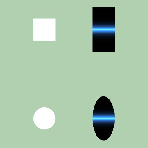
頂点シェーダーでpos.y *= 2.0;として、y方向に2倍拡大した図形を描画できているはずです。
`pos.y -= 0.5;としているのは、元々の図形の中心が(x, y)=(0.5, 0.5)なので、拡大後の中心をそこに合わせるためです。
図形の回転
ここまでで移動、拡大ができるようになりました。 少しだけ難易度を上げて、図形を回転させてみましょう。
let vs = `
   precision highp float;

   attribute vec3 aPosition;
   attribute vec2 aTexCoord;
   varying vec2 vTexCoord;

   uniform mat4 uProjectionMatrix;
   uniform mat4 uModelViewMatrix;

   mat2 rotate2d(float _angle){
      return mat2( cos(_angle), sin(_angle),
                  -sin(_angle), cos(_angle) );
   }

   uniform float u_angle;

   void main() {
      vec3 pos = aPosition;
      pos.xy -= 0.5 ;
      pos.xy = rotate2d(u_angle) * pos.xy;
      pos.xy += 0.5;
      vec4 positionVec4 = vec4(pos, 1.0);

      vTexCoord = aTexCoord;

      gl_Position = uProjectionMatrix * uModelViewMatrix * positionVec4;
   }
`;

let fs = `
   precision highp float;

   varying vec2 vTexCoord;

   void main() {
      vec2 b = vTexCoord * 2.0 - 1.0;
      vec3 col = vec3(pow(1.0 - abs(b.y), 8.0) * 2.0);
      col *= vec3(0.2, 0.5, 0.9) ;

      gl_FragColor = vec4(col, 1.0);
    }
`;

let theShader;

function setup() {
   createCanvas(500, 500, WEBGL);

   theShader = createShader(vs, fs);

   rectMode(CENTER);
   noStroke();

   const wh = 75 ;

   background("#B0D0B0");

   shader(theShader);

   theShader.setUniform('u_angle', radians(30));
   push();
   translate(100, -150);
   rect(0, 0, wh, wh);
   pop();

   theShader.setUniform('u_angle', radians(60));
   push();
   translate(100, 150);
   ellipse(0, 0, wh, wh);
   pop();

   resetShader();

   push();
   translate(-100, -150);
   rotate(radians(30));
   rect(0, 0, wh, wh);
   pop();

   push();
   translate(-100, 150);
   rotate(radians(60));
   ellipse(0, 0, wh, wh);
   pop();
}
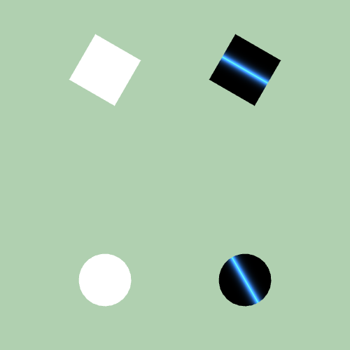
p5.jsから回転させる角度をu_angleで指定して、図形を回転させています。
図形の回転は
pos.xy = rotate2d(u_angle) * pos.xy;
として、行列演算をして座標変換を行っています。
回転行列は次のように定義されます。
   mat2 rotate2d(float _angle){
      return mat2( cos(_angle), sin(_angle),
                  -sin(_angle), cos(_angle) );
   }
これらで図形の回転を実現しています。
前後で0.5を足したり、引いたりする意味は、
中心を(0.5, 0.5)から(0, 0)に移動させて、回転処理。 その後(0.5, 0.5)に戻しています。
      pos.xy -= 0.5 ;
      pos.xy = rotate2d(u_angle) * pos.xy;
      pos.xy += 0.5;
演算の中の詳しい説明が気になる方は調べてみてください。
図形の変形
最後に図形の変形を行います。
let vs = `
   precision highp float;

   attribute vec3 aPosition;
   attribute vec2 aTexCoord;
   varying vec2 vTexCoord;

   uniform mat4 uProjectionMatrix;
   uniform mat4 uModelViewMatrix;

   void main() {
      vec3 pos = aPosition;
      pos.y += (pos.x < 0.5) ? 0.5 : -0.5 ;
      vec4 positionVec4 = vec4(pos, 1.0);

      vTexCoord = aTexCoord;

      gl_Position = uProjectionMatrix * uModelViewMatrix * positionVec4;
   }
`;

let fs = `
   precision highp float;

   varying vec2 vTexCoord;

   void main() {
      vec2 b = vTexCoord * 2.0 - 1.0;
      vec3 col = vec3(pow(1.0 - abs(b.y), 8.0) * 2.0);
      col *= vec3(0.2, 0.5, 0.9) ;

      gl_FragColor = vec4(col, 1.0);
    }
`;

let theShader;

function setup() {
   createCanvas(500, 500, WEBGL);

   theShader = createShader(vs, fs);

   rectMode(CENTER);
   noStroke();

   const wh = 75 ;

   background("#B0D0B0");

   shader(theShader);

   push();
   translate(100, -150);
   rect(0, 0, wh, wh);
   pop();

   push();
   translate(100, 150);
   ellipse(0, 0, wh, wh);
   pop();

   resetShader();

   push();
   translate(-100, -150);
   rect(0, 0, wh, wh);
   pop();

   push();
   translate(-100, 150);
   ellipse(0, 0, wh, wh);
   pop();
}
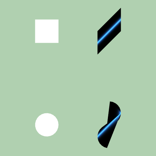
条件によって、頂点の演算を変えてています。 今回はx座標が0.5より小さいかどうかで、移動方向を変えました。
pos.y += (pos.x < 0.5) ? 0.5 : -0.5 ;
x座標の右半分と左半分で画面の上下に移動する方向を変えてみました。 変形後は斜めにずらしたような形になっています。
まとめ
今回はp5.jsの図形をGLSLの頂点シェーダーで移動、拡大、回転、変形させてみました。 これで、頂点を扱うことができるようになり、表現できる図形の形が増えたはずです。 応用すれば、おもしろいものが作れるのではないでしょうか。
参考文献
p5.jsでのシェーダー(GLSL)入門
p5.jsでのシェーダー(GLSL)入門(1)描画してみる - ギンGraphic
p5.jsでのシェーダー(GLSL)入門(2)図形にシェーダーを適用 - ギンGraphic